Integration guide
About this guide
This is a technical guide for connecting physical battery systems to the Tensor Cloud battery optimization service. It is aimed at:
- System integrators implementing battery optimization solutions
- EMS developers building gateway connections to Tensor Cloud
- Technical stakeholders responsible for energy storage system operations
This guide consists of two parts: The guide itself, and communication protocol specifications in AsyncAPI format. The guide provides an overview of the integration process, technical requirements, and operational responsibilities. The AsyncAPI specification contains detailed message schemas, telemetry requirements, and command structures.
We highly recommend making yourself familiar with the AsyncAPI specification before starting the integration process, as it contains all necessary details on the communication protocol, and guidance on automatic client code generation.
Before building an integration with Tensor Cloud, make sure you contact our technical team for detailed guidance and for getting access to a Tensor Cloud development workspace.
About Tensor Cloud
The battery optimization API enables automated, intelligent management of battery energy storage systems through real-time communication between Tensor Cloud's optimization engine and on-site Energy Management Systems (EMS). It aims to maximize the value of battery storage systems by creating economically optimal charge/discharge schedules.
It does this by aggregating technical signals from the battery system and other on-site hardware, and combining them with economic signals from electricity markets and other sources to arrive at an economically optimized battery operating schedule.
For the physical control of the battery system, and for collecting site telemetry, Tensor Cloud relies on EMS operated and provisioned by specialized providers. While Tensor Energy has a number of established partners that can handle physical integration at any scale, we are vendor agnostic within the limits of technical feasibility.
System overview
Note that Tensor Cloud currently only supports a single battery, solar system, and electrical load per site.
Use cases
Tensor Cloud supports three main use cases for battery optimization: AC-link, DC-link, and stand-alone.
Each use case has different requirements when it comes to required telemetry data that the EMS needs to send. Refer to the telemetry section for details.
AC-linked battery systems
This is often the case for retrofit FIP-conversion projects where the original solar topology cannot be fundamentally changed without losing FIT/FIP certification. The battery and solar system exchange energy through their respective inverters, with an optional on-site electrical load also connected via AC.
DC-linked battery systems
In DC-linked systems, the battery and solar PV are connected on the DC side, allowing for more efficient energy transfer. An optional on-site electrical load is also supported. This use-case is common in new installations where the system can be designed from the ground up to optimize for battery integration.
Stand-alone battery systems
Stand-alone battery systems are not co-located with solar or electrical loads. They often operate as merchant systems for exclusive participation in energy markets.
Technical requirements
Communication
The communication protocol used by Tensor Cloud for battery optimization is MQTT (Message Queuing Telemetry Transport) 3.1.1 over TLS 1.2+. This protocol is designed for lightweight, reliable pub/sub information exchange between the EMS and Tensor Cloud.
Endpoints
The Tensor Cloud battery optimization service is accessible via the following MQTT broker endpoints:
Testing environment: mqtt.staging.tensorenergy.jp:8883
Production environment: mqtt.tensorenergy.jp:8883
The testing environment is used during the integration development phase and for post-integration testing. The production environment is used for live operations once the integration is complete and validated.
Authentication
Tensor Cloud uses X.509 certificates for secure authentication with our MQTT broker. Each EMS gateway or software application must have its own unique certificate. Your technical contact at Tensor Energy will provide certificates for development and production environments on request within 24 hours.
Certificates are scoped to specific topics on the MQTT broker, which means that each certificate can only publish and subscribe to the topics it is authorized for. This ensures that your EMS can only interact with the data and commands relevant to the site it is installed at.
QoS (Quality of Service)
Tensor Cloud supports MQTT QoS levels 0 and 1 for message delivery. This means that messages are delivered at most once (QoS 0) or at least once (QoS 1). If your client library supports QoS 1, explicit acknowledgement messages are not required, as the MQTT protocol will handle message delivery guarantees.
MQTT topics
All communication between the EMS and Tensor Cloud is done through MQTT topics in a publish/subscribe fashion. The topic structure is designed to be intuitive and follows a hierarchical format based on site and device identifiers.
Site ID and Gateway ID
Understanding the relationship
- Site ID (
siteId): Represents a single physical installation location (e.g., one battery storage facility). This identifier is used for command topics since commands are sent to the site level. - Gateway ID (
gatewayId): Represents a specific EMS device or software instance that collects telemetry and executes commands for a site. This identifier is used in telemetry topics to distinguish which gateway device is reporting.
Common configurations
-
Single gateway per site (typical): One physical EMS device installed at the site
- Example: Site
ABC123has gatewayGW001 - All telemetry from this site uses
dt/ABC123/GW001/... - Commands are sent to
cmd/ABC123/...
- Example: Site
-
Hot standby: Both primary and standby devices are connected to the MQTT broker
- Example: Site
ABC123has gatewaysGW001(primary) andGW002(standby) - Both devices subscribe to
cmd/ABC123/... - Only the active device publishes telemetry using
dt/ABC123/GW001/... - On failure, standby takes over and publishes using
dt/ABC123/GW002/... - Each gateway has its own unique certificate
- Example: Site
-
Cold standby: Only the primary device is connected to the MQTT broker
- Example: Site
ABC123has gatewaysGW001(primary) andGW002(standby) - Primary publishes telemetry using
dt/ABC123/GW001/... - Standby device is physically on site but NOT connected to the broker
- On primary failure, standby connects and publishes using
dt/ABC123/GW002/... - Each gateway has its own unique certificate
- Example: Site
Important notes
- Each certificate can publish/subscribe to topics for only the sites it is authorized for
- For redundancy setups, each physical gateway device must have its own certificate
- One certificate can only be used for one concurrent connection to the broker
Overview
Telemetry
Site hardware telemetry (e.g., site meter discharge, solar generation, battery SoE) is published by the EMS using a unified dt/ topic prefix, followed by the site ID, gateway ID, and an ending specific to the type of telemetry (lifetime, windowed, instantaneous), resulting in the following formats:
Lifetime metric topic structure:
dt/{siteId}/{gatewayId}/{metric}/lifetime

Windowed metric topic structure:
dt/{siteId}/{gatewayId}/{metric}/energy/{window}

Instantaneous metric topic structure:
dt/{siteId}/{gatewayId}/{metric}/power
The Site ID and Gateway ID are unique identifiers assigned to each site and its associated EMS gateway. They will be provided to you by your technical contact at Tensor Energy together with each set of certificates.
For a list of telemetry types and their definitions, see the tables below and the protocol schema.
Telemetry Data Types
Tensor Cloud supports three types of telemetry data for each metric. The following table shows the relationship between data types, MQTT topic patterns, formats, and requirements:
| Type | MQTT Topic Pattern | Unit | Value Semantics | Required? |
|---|---|---|---|---|
| Instantaneous power | dt/{siteId}/{gatewayId}/{metric}/power | kW | Instantaneous power value at measurement time. All values ≥ 0 (direction encoded in metric name). | ⚪️ Optional - can enhance accuracy when sent at high frequency (≤10 min), but cannot replace energy readings. |
| Windowed energy | dt/{siteId}/{gatewayId}/{metric}/energy/{window} | kWh | Energy consumed/generated during a specific time window (e.g., PT30M = 30 minutes). All values ≥ 0. | 🟡 Required (either this OR lifetime) - at least one energy reading type must be sent for optimization to work. |
| Lifetime energy | dt/{siteId}/{gatewayId}/{metric}/lifetime | kWh | Cumulative energy since commissioning (increasing counter, similar to electricity meter). Tensor Cloud handles counter resets. All values ≥ 0. | 🟡 Required (either this OR windowed) - at least one energy reading type must be sent for optimization to work. |
EMS must send at least one energy reading type (windowed OR lifetime) for Tensor Cloud battery optimization to function correctly. Instantaneous power readings are optional and can improve accuracy when sent frequently, but cannot replace energy readings.
Common to all use cases
| Telemetry name | Required/Optional | Description |
|---|---|---|
meter_export_ac | 🔴 Required | Amount of energy exported to the grid measured at the main site meter. |
meter_import_ac | 🔴 Required | Amount of energy imported from the grid measured at the main site meter. |
battery_soe | 🔴 Required | State of Energy (SoE) in kWh of the battery system. This is the amount of energy currently stored in the battery at this moment (kWh equivalent of State of Charge). Valid range: 0 ≤ battery_soe ≤ battery_energy_remaining. |
battery_energy_remaining | 🔴 Required | Total usable energy capacity of the battery system in kWh at nominal temperature (usually ~25°C) accounting for cell degradation and faulty cells. This represents the maximum energy the battery can hold and should be updated when capacity changes due to degradation or temperature effects. Unlike battery_soe which changes frequently, this value typically updates once per day or when significant capacity changes occur. |
grid_to_load_ac | ⚪️ Optional | Amount of energy sent from the site meter to an on-site electrical load (e.g., factory). Required if on-site load exists. |
load_demand_ac | ⚪️ Optional | Total amount of energy consumed by an on-site electrical load (e.g., factory). Sum of grid_to_load_ac and either battery_to_load_ac for AC-link, or inverter_to_load_kwh for DC-link. Required if on-site load exists. |
curtailment | ⚪️ Optional | Curtailment schedule by the TSO captured by the EMS from the on-site curtailment device. |
Understanding battery capacity metrics
| Metric | Description | Send to Tensor Cloud |
|---|---|---|
battery_energy_remaining | Effective battery capacity in kWh accounting for degradation and faulty cells | Once per day |
battery_soe | Current energy stored in battery (kWh). Calculate as: SoC% × battery_energy_remaining | Every 1-10 minutes |
When calculating battery_soe from SoC percentage, always multiply by battery_energy_remaining (effective capacity), not nominal capacity.
Example: Battery with 3,000 kWh nominal capacity, degraded to 2,800 kWh effective capacity, at 50% SoC:
- Correct:
battery_soe = 50% × 2,800 kWh = 1,400 kWh - Wrong:
battery_soe = 50% × 3,000 kWh = 1,500 kWh(will cause incorrect optimization)
AC-linked battery systems
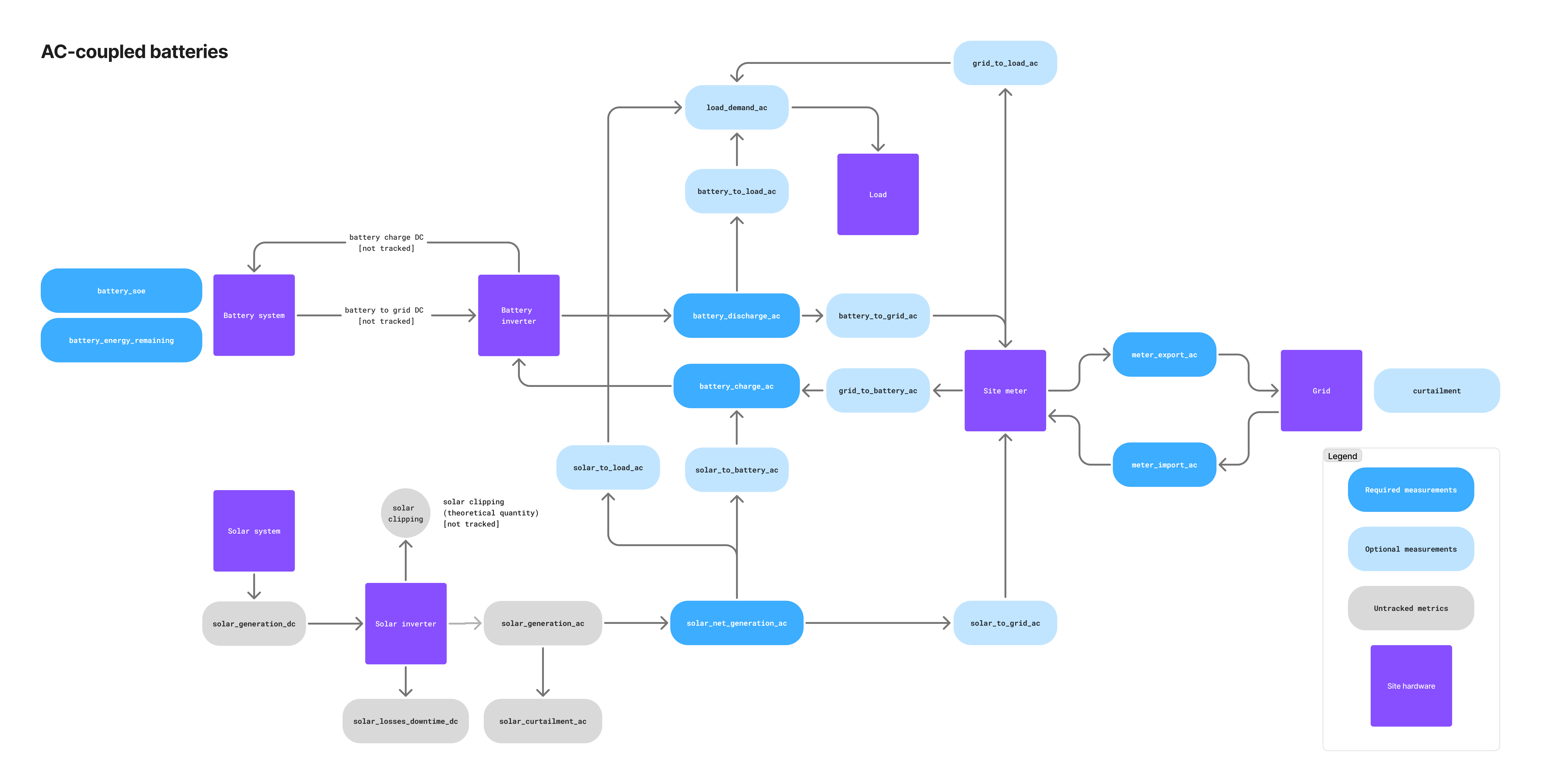
| Telemetry name | Required/Optional | Description |
|---|---|---|
solar_net_generation_ac | 🔴 Required | Solar generation after subtracting curtailment. Sum of solar_to_load_ac, solar_to_battery_ac, and solar_to_grid_ac. |
battery_charge_ac | 🔴 Required | Amount of energy charged into the battery system, usually measured at the battery meter or monitoring system. Sum of grid_to_battery_ac and solar_to_battery_ac. |
battery_discharge_ac | 🔴 Required | Amount of energy discharged from the battery system, usually measured at the battery meter or monitoring system. Sum of battery_to_grid_ac and battery_to_load_ac. |
solar_to_grid_ac | ⚪️ Optional | Amount of energy sent directly from the solar system to the site meter. |
solar_to_battery_ac | ⚪️ Optional | Amount of energy sent from the solar system to the battery. |
solar_to_load_ac | ⚪️ Optional | Amount of energy sent from the solar system to an on-site electrical load (e.g., factory). |
battery_to_grid_ac | ⚪️ Optional | Amount of energy sent from the battery to the grid measured at the main site meter. |
battery_to_load_ac | ⚪️ Optional | Amount of energy sent from the battery to an on-site electrical load (e.g., factory). |
grid_to_battery_ac | ⚪️ Optional | Amount of grid energy sent to the battery measured at the main site meter. |
DC-linked battery systems
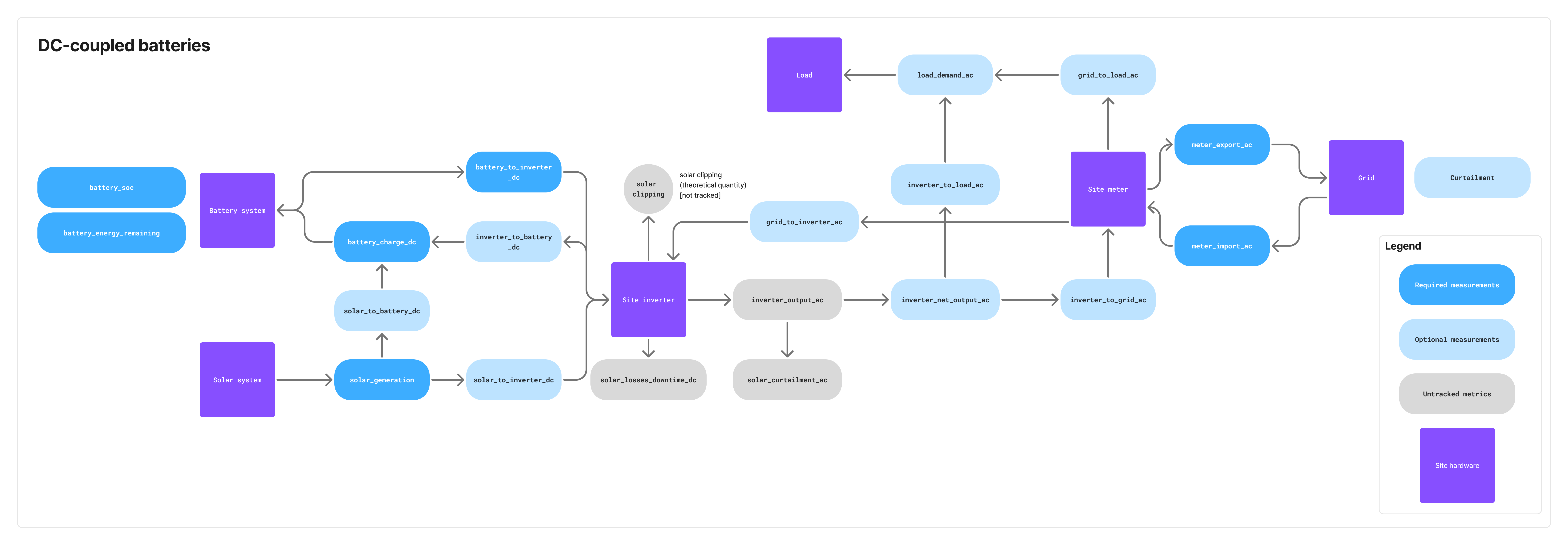
| Telemetry name | Required/Optional | Description |
|---|---|---|
solar_generation_dc | 🔴 Required | Amount of energy generated by the solar system measured on the DC side. Sum of solar_to_battery_dc and solar_to_inverter_dc. |
battery_charge_dc | 🔴 Required | Amount of energy charged into the battery system measured on the DC side. Sum of solar_to_battery_dc and inverter_to_battery_dc. |
battery_to_inverter_dc | 🔴 Required | Amount of energy sent from the battery to the site inverter. Measured on the DC side. |
inverter_net_output_ac | ⚪️ Optional | Net output of the site inverter. This is the amount of energy sent from the inverter to the grid minus the amount of energy received from the grid. Measured on the AC side. Sum of inverter_to_load_ac and inverter_to_grid_ac. Required in case of an on-site electrical load. |
solar_to_battery_dc | ⚪️ Optional | Amount of energy sent from the solar system to the battery. Measured on the DC side. |
solar_to_inverter_dc | ⚪️ Optional | Amount of energy sent from the solar system to the site inverter. Measured on the DC side. |
inverter_to_battery_dc | ⚪️ Optional | Amount of energy sent from the inverter to the battery. Measured on the DC side. |
inverter_to_load_ac | ⚪️ Optional | Amount of energy sent from the inverter to an on-site electrical load (e.g., factory). Measured on the AC side. Required if on-site load exists. |
inverter_to_grid_ac | ⚪️ Optional | Amount of energy sent from the inverter to the grid. Measured on the AC side. |
grid_to_inverter_ac | ⚪️ Optional | Amount of grid energy sent to the inverter. Measured on the AC side. Required if the battery system can charge from the grid. |
Stand-alone battery systems
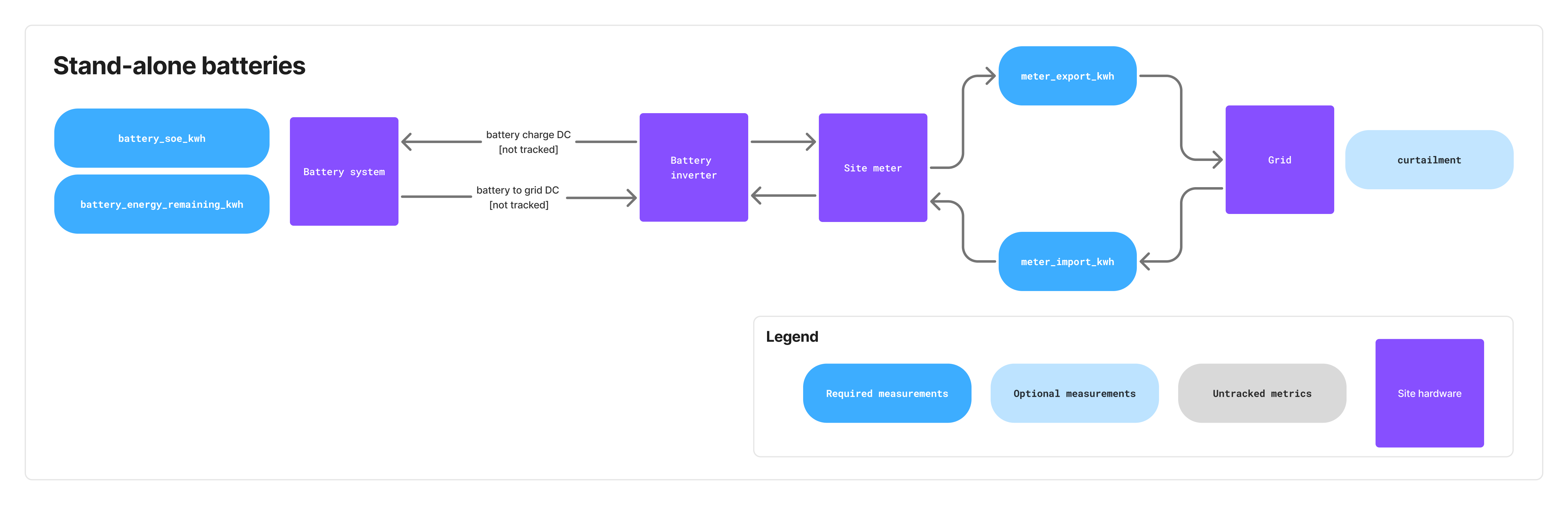 Stand-alone battery systems only require the telemetry listed in the "Common to all use cases" section above.
Commands
Commands (e.g., containing charge/discharge schedules for the battery or FCR bid schedules) are sent by Tensor Cloud using a unified cmd/ topic prefix, followed by the site ID and command type, resulting in the following formats:
Battery power setpoint commands:
cmd/{siteId}/battery/power

Battery FCR bid commands:
cmd/{siteId}/battery/fcr
For a list of command types and their definitions, see the protocol schema.
Command lifecycle sequence
The acknowledgment (ack-cmd) should be sent immediately after receiving and parsing the command, not at execution time.
Alerts
Alerts communicate fault and status conditions from the EMS to Tensor Cloud. Two complementary channels are used:
dt/{siteId}/{gatewayId}/alert(alertEvent) → Delta updates when an alert changes state (inactive → activeoractive → inactive).dt/{siteId}/{gatewayId}/alert/active(alertState) → Periodic full snapshot of all currently active alerts.
Tensor Cloud consumes both channels:
alertEventenables fast reaction to alert changes.alertStateensures robustness if any events are lost and allows reconstruction of the full active state.
Flow of alert messages
- When a hardware register transitions
0 → 1, EMS publishes analertEventwithmeasurement_value.status = active. - On the next snapshot, EMS publishes an
alertStateincluding this active alert (EMS must publish alertState at least every 10 minutes or at system startup, whichever comes first). - When a register transitions
1 → 0, EMS publishes analertEventwithmeasurement_value.status = cleared. - While an alert remains active, EMS updates
last_seen_tsfor that alert in everyalertState.
Alert codes reference
| Code | Subsystem | Explanation |
|---|---|---|
BATT_SOC_LOW | Battery | Battery state of charge has fallen below the minimum threshold, risking insufficient energy availability for operations. |
BATT_SOH_DEGRADED | Battery | Battery state of health is degraded compared to expected performance, indicating aging or damage that may require replacement planning. |
BATT_OVERTEMP | Battery | Battery temperature has exceeded safe operating limits, increasing the risk of accelerated degradation or thermal damage. |
BATT_COMM_FAIL | Battery | The EMS cannot communicate with the Battery Management System (BMS); the battery may still operate, but status and control are unavailable. |
BATT_OTHER | Battery | Any battery-related fault that does not fall into defined categories. |
PV_COMM_FAIL | Solar PV | The EMS cannot communicate with the inverter; the inverter may continue operating, but monitoring and control functions are unavailable. |
PV_OTHER | Solar PV | Any solar PV–related fault that does not fall into defined categories. |
CURT_COMM_FAIL | Grid/TSO | The EMS lost communication with the curtailment device, preventing TSO curtailment schedules from being acquired. |
UNKNOWN_FAULT | Unknown | Fault has been reported, but its type is not recognized or mapped to existing alert codes. Please contact the Tensor Energy technical team during the development phase to discuss including your alert code in this list. |
Payload format
All messages published to the MQTT broker use JSON format. The payload structure is defined in the protocol schema, which includes telemetry messages and command formats expressed in JSON schema. The schema provides detailed definitions for each message type, including required fields, data types, and validation rules.
Timestamp boundary convention
All time windows in the protocol use left-inclusive, right-exclusive boundaries: [start_ts, end_ts)
This convention applies to:
- Windowed energy telemetry (
measurement_value.start_tsandmeasurement_value.end_ts) - Curtailment schedules (
start_tsandend_ts) - Battery power command schedules (
control.schedule[].start_tsandcontrol.schedule[].end_ts) - FCR bid command schedules (
control.schedule[].start_tsandcontrol.schedule[].end_ts)
Example: A time window with end_ts of 2024-01-04T10:30:00.000+09:00 includes all times up to but not including 10:30:00. This means it includes 10:29:59.999... but not 10:30:00.000.
This convention ensures adjacent time windows connect seamlessly without gaps or overlaps:
- Window 1:
[10:00:00, 10:30:00)→ includes 10:00:00, excludes 10:30:00 - Window 2:
[10:30:00, 11:00:00)→ includes 10:30:00, excludes 11:00:00
Command schedule prioritization
Tensor Cloud sends battery control commands in two types:
Battery power setpoint schedules
Battery charge/discharge schedules are sent in two prioritized layers to cmd/{siteId}/battery/power:
- Every 30 minutes at minutes 15 and 45, a schedule covering the next 48 hours with one setpoint per 30 minutes is sent with the priority 2
- Every Monday, Wednesday, and Friday at 6 am Japan time, a simplified long-term schedule covering 1 year with 3 setpoints per day is sent with priority 1
The power setpoint schedule is also be used to relay balancing market commands from Japan's TSO balancing command system (簡易指令システム) to each EMS. These commands are sent as they are received by Tensor Cloud by the TSO.
Battery FCR bid schedules
FCR (Frequency Containment Reserve) bid schedules are sent to cmd/{siteId}/battery/fcr and specify the capacity to offer for frequency regulation services. Each schedule item includes:
- Time window (start/end timestamps in 3-hour blocks: 6-9am, 9am-12pm, etc.)
- Capacity in kW to bid (minimum 1000 kW)
FCR schedules are not sent at regular intervals and usually do not include fallback schedules. They are only sent when there are confirmed bids in the balancing market.
Cancelling FCR commands
FCR commands can be cancelled by sending a new command with action: "cancel" and specifying the time range to cancel. The cancellation:
- Respects priority rules: only cancels commands with equal or lower priority
- Can cancel arbitrary time periods (single 3-hour blocks, multiple days, weeks, etc.)
- Does not require
capacity_kwfield (only time range needed)
Cancellation is used when market bids have been canceled (e.g., because required battery SoC levels cannot be reached). Bids can be canceled up to 1 hour before delivery (gate closure).
Schedule interpretation rules
When interpreting all command schedules (power setpoint and FCR), the EMS must adhere to the following rules:
- Execute higher priority over lower priority schedules
- If schedules covering the same time period have the same priority, execute the one with the most recent
issue_tstimestamp
All command messages include an issue_ts field, which is an ISO-8601 compliant timestamp indicating when the command was issued by Tensor Cloud. This timestamp is essential for determining which command to execute when multiple commands with the same priority cover the same time period.
Command execution priority logic
If the EMS does not regularly send required telemetry, Tensor Cloud will stop generating battery charge/discharge schedules.
Message timing
Telemetry publishing requirements
| Message Type | Minimum Frequency | Recommended Frequency |
|---|---|---|
| Energy telemetry (windowed/lifetime) | Every 10 minutes | Every 1 minute |
| Instantaneous power (if available) | Same as energy or faster | Every 1 minute or faster |
Battery state (battery_soe) | Every 10 minutes | Every 1 minute |
battery_energy_remaining | Once per day | Once per day |
Alert snapshot (alertState) | Every 10 minutes | Every 5 minutes |
Alert events (alertEvent) | Immediately on state change | N/A |
| Curtailment schedules | On update from TSO | N/A |
Key principles
- Different telemetry types should be published independently as they become available
- Alert events must be published immediately when hardware registers change state
- Alarm conditions or significant state changes should trigger immediate publishing
Error handling
Telemetry errors
In case the EMS is unable to send site telemetry data to Tensor Cloud (e.g., due to malformed commands or communication issues), the EMS application logic should follow these guidelines:
- Retain telemetry data locally and attempt retransmission when the network is available
- Log the error details for analysis
- Implement exponential backoff strategies to avoid rate limits on the MQTT broker
- Prioritize recent telemetry data over sending retained data in bulk
Command errors
If the EMS receives a command that it cannot process (e.g., due to malformed JSON or unsupported parameters), or, if it does not receive any command schedule (e.g., due to communication issues), it should:
- Respond in the
ack-cmd/{siteId}topic with an appropriate error message - Continue executing the previous valid schedule until the error is resolved in order of priority and time
Error Codes
The protocol uses standardized error codes across all error surfaces:
MESSAGE_MALFORMED: Message is not valid JSONMISSING_FIELD: Required field is missingTYPE_MISMATCH: Field has incorrect typeFIELD_OUT_OF_RANGE: Numeric value outside valid rangeTIME_WINDOW_INVALID: Invalid time window or schedule (e.g., start time is after end time)DUPLICATE: Duplicate message or identifier (e.g., message with same id sent twice)EXPIRED: Message or command has expired (e.g., schedule starts and ends in the past)RESOURCE_UNAVAILABLE: Required resource is unavailable (e.g., connection between EMS and battery system is severed)INTERNAL_ERROR: Internal system error not covered by other error types
Error Surfaces
- CommandResponse.errors[]: Machine-actionable command execution results
- TelemetryFeedback.code: Validation error codes (staging only)
Testing environment
To make it easier for EMS integrators to validate their implementation, Tensor Cloud provides a testing environment. The differences between the production and testing environments are:
- Complete isolation in terms of data and operations between both environments
- In testing, Tensor Cloud will respond to all telemetry messages from EMS devices with an explicit
error/okresponse in topicack-dt/{siteId}/{gatewayId}/telemetry
Responsibility model
Tensor Cloud works under a shared responsibility model with its partners and battery system owners. Each party has specific roles and responsibilities in the integration and operation of the battery optimization service.
| Party | Responsibilities |
|---|---|
| Tensor Energy | • Economic optimization and schedule generation • Soft guarantees of battery system owner preferences (e.g., min/max SoE) |
| Integrator/EMS | • EMS uptime management and guarantees in alignment with battery owner • Accurate telemetry reading from site hardware according to the protocol specifications • Local enforcement of TSO constraints (e.g., battery ramp rates, curtailment, data logging requirements) • Hard guarantees of battery system owner preferences (e.g., min/max SoE) • Emergency response and EMS hardware fault handling |
| Battery system owner | • Imbalance responsibility (depending on contract terms, this could be shared with Tensor Energy) • Relationship management with TSO and other stakeholders like OCCTO (depending on contract terms, this could be shared with Tensor Energy) |
| Battery OEM | • Hardware maintenance and support (depending on contract terms with battery system owner) • Battery firmware updates and bug fixes |
Implementation process
1. Initial reach out
If you are interested in integrating with Tensor Cloud's battery optimization service, please start by contacting us through our website contact form. Our team will get back to you with a schedule for an initial meeting to discuss the details of your integration project. Depending on the complexity of your use case, multiple meetings may be required at this point.
We also recommend early conversations, involving Tensor Energy representatives, with the battery system owner to discuss their operational and economic requirements, and any specific constraints that may affect the integration process.
2. Certificate setup
After the initial meeting, our technical team will provide you with an initial set of development X.509 certificates for secure authentication with our staging MQTT broker.
3. Integration phase
Depending on the maturity and flexibility of your EMS solution, expect the integration process to take anywhere from a few days to several months. During that process, our technical team can provide support for establishing an initial connection to our MQTT broker, and for answering any questions the communication protocol.
If there are any customizations required on our end, our team will synchronize this work with your development timeline to the best of our ability.
4. Testing and validation
Once the initial integration is complete, we will coordinate with you to perform integration testing. This includes
- Validating telemetry data publishing
- Testing command processing and response
- Ensuring proper error handling and recovery mechanisms
Contact your technical representative at Tensor Energy for details on the testing process.
Resources
- AsyncAPI schema file: Download JSON
- Protocol specifications: Online documentation